


** Notice ** The pictures in this install guide were taken with the red 3M Scotchlok taps. An optional No-Cut installation kit is available with Posi-Tap wire taps instead of the red 3M Scotchlok taps. For detailed instructions on how to use the Posi-Taps, please visit their website.
There are seven wires that need to be connected to the vehicles wiring harnesses. SettingSaver has two wiring harnesses, one 3-wire harness and one 4-wire harness. The SettingSaver 4-wire harness goes under the console box and connects to the DCCD/SI-Drive wiring harness. The SettingSaver 3-wire harness goes under the steering wheel to the VDC/TC switch and to power. The power wire must be connected to a fused +12V Ignition switched power source. This can be easily found at the fuse box behind the VDC switch by using an "Add-a-Circuit" fuse tap into fuse position #32. If the SettingSaver is powered by an Accessory switched power source you will experience unwanted results as the power is cut during the engine start rebooting the SettingSaver. Below is a list of tools that will make your life a little easier when installing your SettingSaver. Installation can take about 1 - 2 hours depending on the level of experience.
- Wide Putty Knife
- Phillips Screw Driver
- Pliers
- Scissors
- Electrical Tape
Connecting the DCCD/SI-Drive Harness
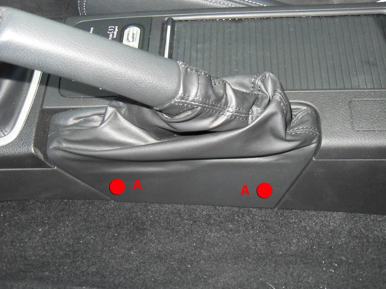
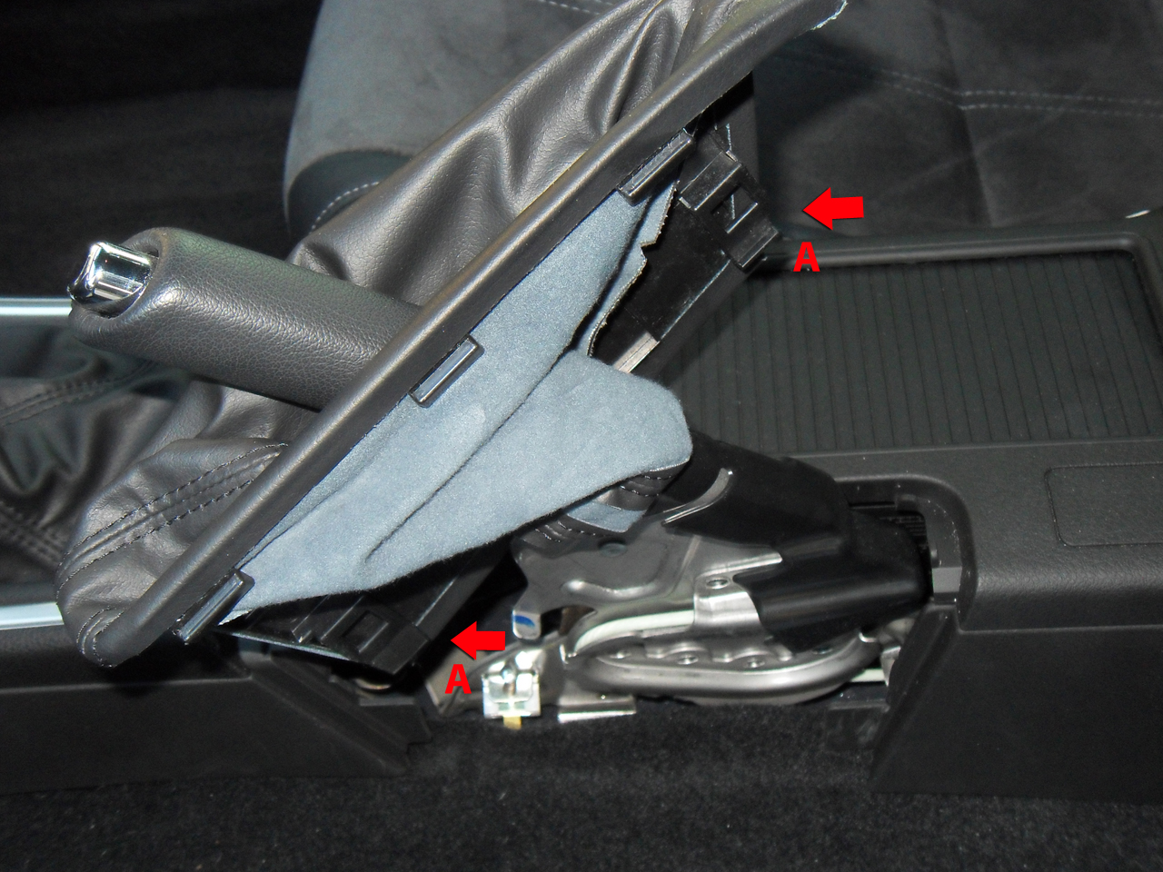
Loosen the parking brake lever boot by pulling it strait up. It may take some force to get it loose. There are two hidden clips (A) that hold the boot to the console box.
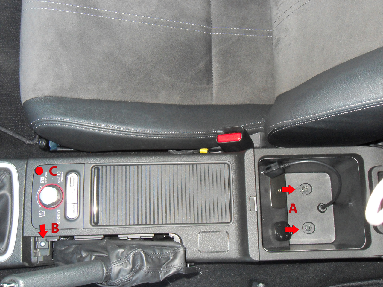
With the parking brake boot loose, remove the two bolts (A) and screw (B, under the parking brake boot) and put them in a safe place. The hidden clip (C) will pop free with an upward tug.
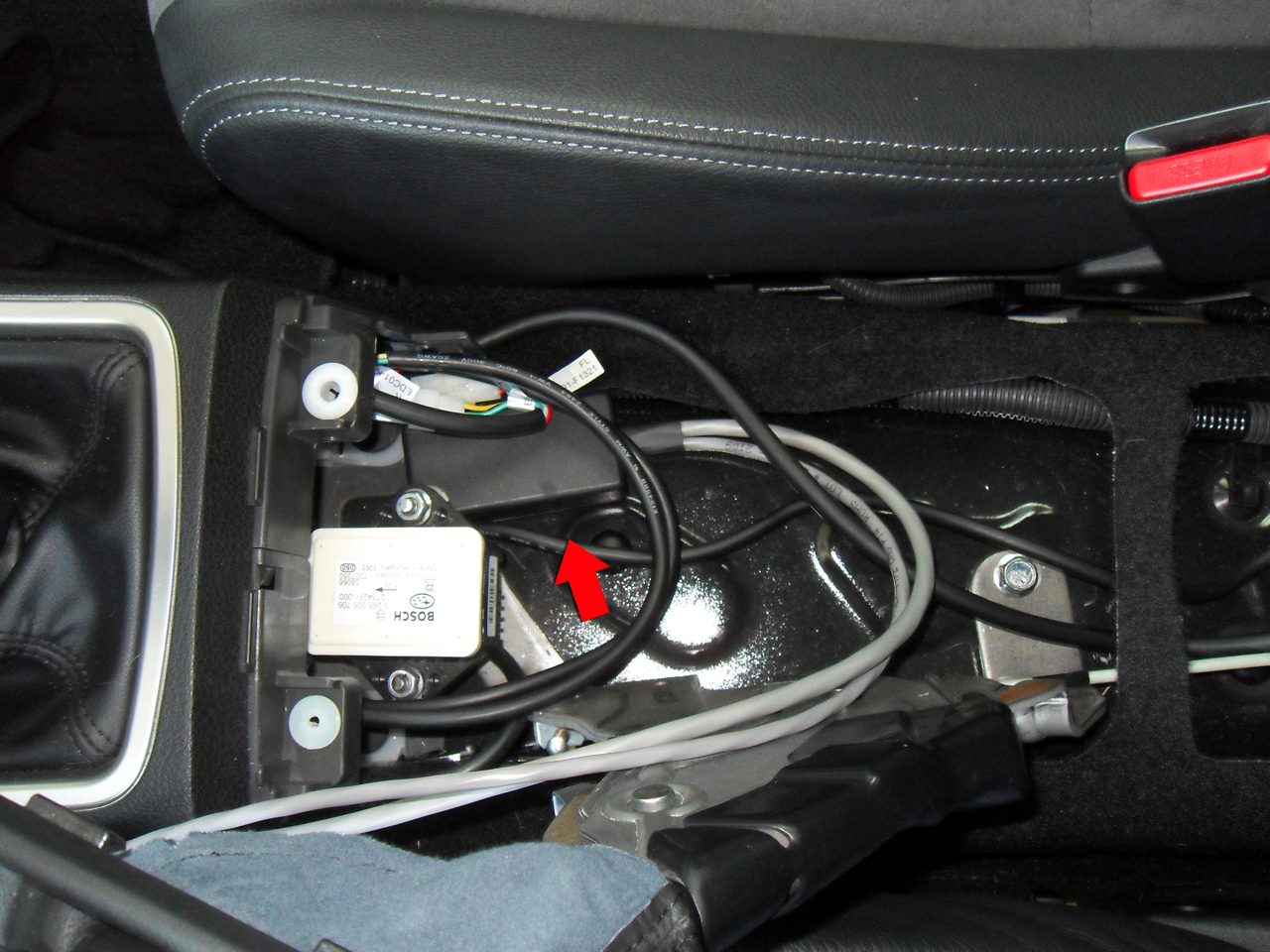
Lift up the console box and locate the DCCD/SI-Drive harness connector. Trace the wires from the DCCD/SI-Drive button to find the harness.
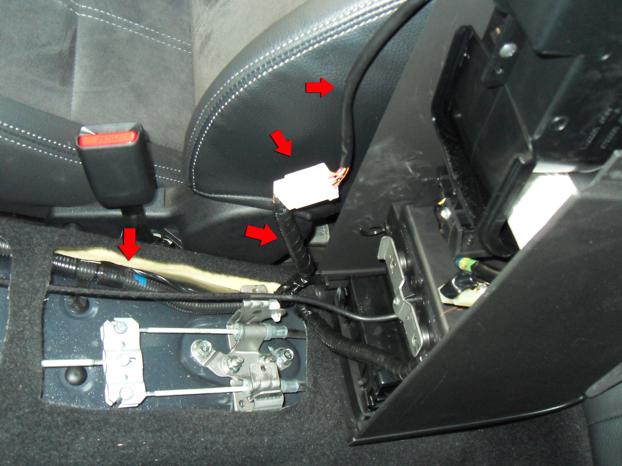
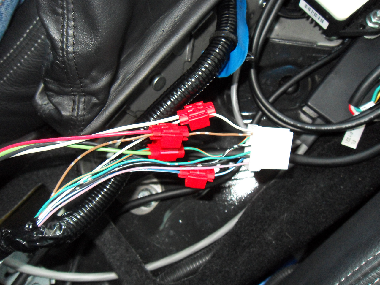
Remove any electrical tape and wiring loom to expose the wires in the harness.
- Black:DCCD AUTO-
- White:DCCD AUTO/MANUAL
- Green:DCCD AUTO+
- Red:SI-Drive
- Blue/White*:DCCD AUTO- (Pin 3)
- White:DCCD AUTO/MANUAL (Pin 1)
- Green/Orange:DCCD AUTO+ (Pin 2)
- Brown:SI-Drive (Pin 5)

- Black --> Blue/White*
- White --> White
- Green --> Green/Orange
- Red --> Brown
Tap the black wire from the SettingSaver 4-wire harness to the blue with white stripe wire from the DCCD/SI-Drive connector. Tap the white wire from the SettingSaver 4-wire harness to the white wire from the DCCD/SI-Drive connector. Tap the green wire from the SettingSaver 4-wire harness to the green with orange stripe wire from the DCCD/SI-Drive connector. Tap the red wire from the SettingSaver 4-wire harness to the brown wire from the DCCD/SI-Drive connector.
Here is a good location for installing the SettingSaver under the console box. Before securing the SettingSaver with tape or velcro, lower the console box to make sure the SettingSaver is out of the way.
Reconnect the DCCD/SI-Drive electrical connector and replace any zip ties that were removed. Install the console box by installing the two bolts (A), screw (B) and clip (C) that were removed earlier. Snap the parking brake boot back in place.
Connecting the VDC Harness
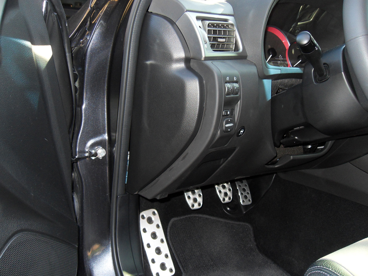
Using a wide putty knife or similar tool, slide the knife under the side panel cover and use a prying action to pop the panel free.
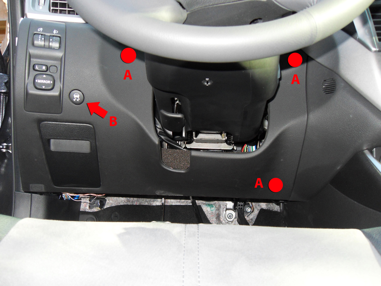
With the side panel cover off locate the two screws holding the instrument panel lower cover to the frame and remove them. Put the screws in a safe place.
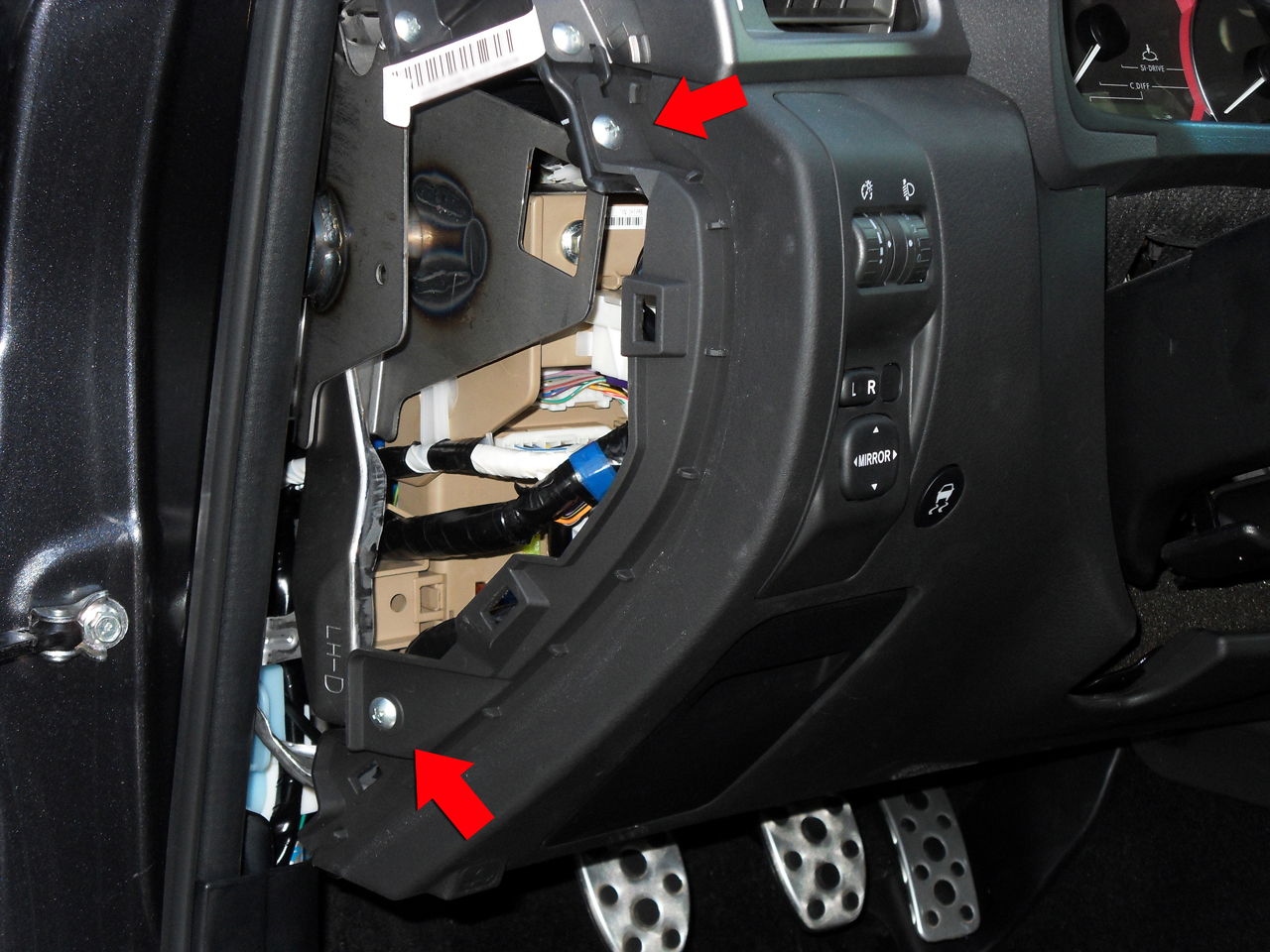
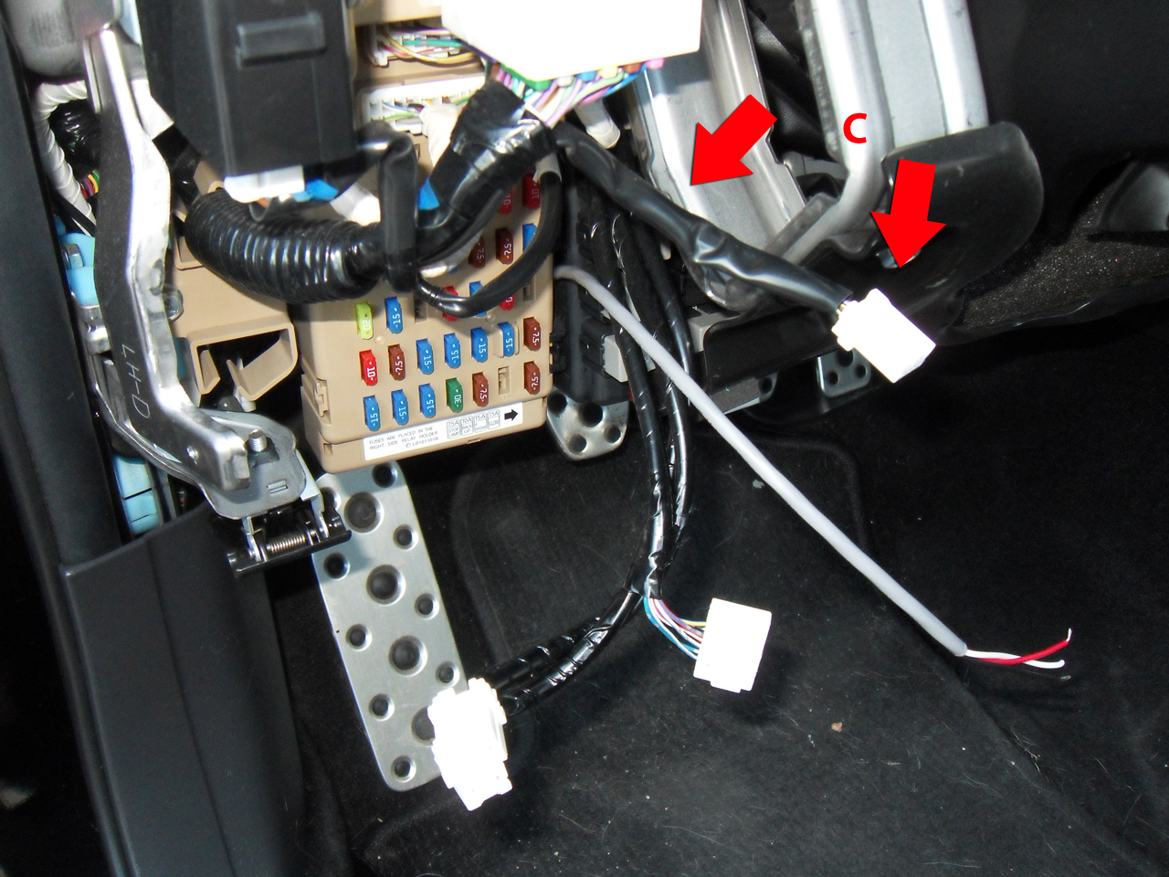
Gently pull on the instrument panel lower cover until all of the hidden clips (A) pop free. Disconnect all of the harness connectors making note of which one plugs into the VDC/TC switch (B) and locate the VDC/TC harness (C).
Remove any electrical tape and wiring loom to expose the wires in the harness.
- White:VDC/TC
- Black:Ground
- Red:IGN +12V
- Orange:VDC/TC (Pin 2)
- Black/Yellow:Ground (Pin 3)

- White --> Orange
- Black --> Black/Yellow
- Red --> Fused IGN +12 Volts
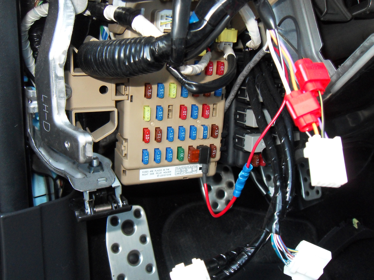
Tap the white wire from the SettingSaver 3-wire harness to the orange wire from the VDC connector. Tap the black wire from the SettingSaver 3-wire harness to the black with yellow strip wire from the VDC connector (*note* the black with white stripe is not a vehicle ground, it is part of the illumination circuit). Connect the red wire from the SettingSaver 3-wire harness to the "Add-a-Circuit" fuse tap using the supplied Posi-Twist connector. Plug the fuse tap into the vehicle fuse box at position #32 with the wire pointing down. The fuse tap will only work in this orientation. Do not use an Accessory power source.
Install the instrument lower panel cover by re-connecting all of the electrical connectors and pop the panel cover back into place. Install the two screws that were removed earlier and snap the instrument side panel cover back in place.
SettingSaver has two modes of operation for each system, Memory mode and Default mode. SettingSaver will be in Memory mode the first time the vehicle is started after installation. Please note that SettingSaver waits for 4 seconds after power up before restoring settings. This is to let the vehicle computers run system checks. After the 4 second delay, SettingSaver will restore settings taking up to 2.5 seconds depending on what settings are being restored. Changing settings during this delay will not be saved and should be avoided. It is also recommended not to engage the vehicles starter during setting restoration (max 2.5 sec) in cold weather. Low battery voltage due to cold weather and starter engagement could result in the vehicle not recognizing a button press made by SettingSaver.
Default Mode
In Default mode, the user defines a system state that the vehicle will always be restored to regardless of the last state it was left in.
To change to Default mode for DCCD make sure the desired DCCD mode is set. Hold the DCCD MANUAL button for at least four seconds. During this button press DCCD will change from AUTO to MANUAL or visa versa. This is normal and will not affect the saved DCCD state. When the DCCD MANUAL button is released, DCCD will revert back to the mode it was in previous to the button press and the SI-Drive indicators will loop counter-clockwise once to indicate that Default mode has been entered.
To change to Default mode for VDC/TC make sure the desired VDC/TC mode is set. Hold the VDC/TC button for at least four seconds. During this button press VDC/TC will change like a normal button press of greater then two seconds. This is normal and will not affect the saved VDC/TC state. When the VDC/TC button is released, VDC/TC will revert back to the mode it was in previous to the button press and the SI-Drive indicators will loop counter-clockwise once to indicate that Default mode has been entered.
To change to Default mode for SI-Drive hold any SI-Drive button for at least four seconds. The SI-Drive mode selected by the button press will be the mode saved as the default setting. When the SI-Drive button is released, the SI-Drive indicators will loop counter-clockwise once to indicate that Default mode has been entered.
Memory Mode
In Memory mode, SettingSaver will restore the vehicles last known system state every time the vehicle is restarted.
To change to Memory mode for DCCD make sure the desired DCCD mode is set. Hold the DCCD MANUAL button for at least four seconds. During this button press DCCD will change from AUTO to MANUAL or visa versa. This is normal and will not affect the saved DCCD state. When the DCCD MANUAL button is released, DCCD will revert back to the mode it was in previous to the button press and the SI-Drive indicators will loop counter-clockwise twice to indicate that Memory mode has been entered.
To change to Memory mode for VDC/TC make sure the desired VDC/TC mode is set. Hold the VDC/TC button for at least four seconds. During this button press VDC/TC will change like a normal button press of greater then two seconds. This is normal and will not affect the saved VDC/TC state. When the VDC/TC button is released, VDC/TC will revert back to the mode it was in previous to the button press and the SI-Drive indicators will loop counter-clockwise twice to indicate that Memory mode has been entered.
To change to Memory mode for SI-Drive hold any SI-Drive button for at least four seconds. The SI-Drive mode selected by the button press will saved. When the SI-Drive button is released, the SI-Drive indicators will loop counter-clockwise twice to indicate that Memory mode has been entered.
If you are having problems with your SettingSaver please try the following steps.
A: Make sure the fuse tap is orientated with the wire facing down. The fuse tap will not supply power if the wire is facing up. Also make sure that the SettingSaver ground wire is connected to a good vehicle ground. Only one ground wire exists in the VDC switch harness. The black with white stripe wire is part of the illumination circuit and is not a ground wire.
Q: My SettingSaver will forget my settings.
A: There may be bad connections at the wire taps. Most problems can be resolved by un-taping and re-taping the connections. It is also possible that the SettingSaver is unknowingly in "Default Mode". In this mode the SettingSaver will not save any changes. Changing the mode to "Memory Mode" will allow the SettingSaver to save changes.